Posts

Frame assembly 2D meshing along with connections.

Image
 Title- Frame assembly 2D meshing along with connections. Aim- To mesh the Frame assembly with 2D meshing and assigning the proper connection such as spot welds, adhesive, and bolt connection. Objective-  Mesh the assembly. assign material and property. assign the connections. check the connectivity. Procedure- Import the geometry into Hypermesh GUI. Have a thorough look at the geometry; either there are any similarities to reflect the other to reduce the time. Split the geometry with the help of organize tab SHIFT+F11. Transfer the items from the basic model to renamed components for proper consideration and visualisation of the geomtrty. As we can reflect some of the parts we will only mesh remaining. Meshing of the components being as follows- Now we will perform the connection for the assembly such as bolts, spots, and adhesives as per the given criterion. Save the file. Conclusion- Meshing on the frame assembly with 2D meshing is successful. All the connections are a...

Linear Static structural analysis of Wheel hub knuckle.

Image
 Title- Linear Static structural analysis of Wheel hub knuckle. Aim- To linear Static structural analysis of Wheel hub knuckle. Objective-  Delete 3 D solids from the geometry To perform required geometry cleanup using defeature tab. To mesh components using 3D volume tetra mesh elements. Set desired boundary condition. Perform linear static analysis. Procedure- Import geometry file into hypermesh solver deck. Delete the solids in geometry. Defeture the small filets and surface irregularities. Now, the meshing process began, firstly volume tetra mesh with R-trias are formed. R-trias are used because it captures the geometry quite well. Rigids are formed in new component rigids. Load collectors with various cases are formed as shown below. various conditions and cases are defined such as- The torque due to braking and driving. Application of brakes. Lateral forces while riding and cornering. Bumps due to road irregularities.      5. Loadsteps    6....

Linear buckling analysis of I shaped column

Image
 Title- Linear buckling analysis of I shaped column Aim- To linear buckling analysis of I shaped column Objective-  To perform required geometry cleanup using defeature tab. To extract the mid surface of the component. To mesh components using 2D elements. Set desired boundary condition. Perform linear static analysis. Perform buckling analysis. Procedure- Import geometry file into hypermesh solver deck. Mid surface extraction and meshing of the component. Also, we need to assign the required thickness from the mid mesh thickness tab. Define the material, property and then assign the proper property to the component. After that boundary conditions are defined. first linear static analysis is performed and those displacement and stress load are imported for buckling analysis via creating an EIGRL load collector. Now the analysis is solved using an Optistruct solver and results will be reviewed with the help of a post-processor hyperview. Conclusion- Structural results impl...

Plastic container meshing in hypermesh.

Image
Title- Meshing of Plastic components in hypermesh pre-processor.  Aim- To perform meshing of Plastic components in hypermesh pre-processor.  Objective-  To perform required geometry cleanup using defeature tab. To mesh component using 2D elements. Procedure- Import geometry file into hypermesh solver deck. Delete the solids- as we know that meshing can be generated either on solids or surfaces. And it's preferred to use surfaces for meshing. Mid surface extraction and Geometry cleanup- Extraction of the mid surface with the help of auto-extract feature with offset+planes. Defeature the surface fillets lesser than the element size so fine mesh can be generated. Meshing- 2D mesh Conclusion- Mesh is created on a given component. Required element criteria are achieved.  Author- Shubham Gangadhar Kurhade. Email-  sgkurhade2511@gmail.com LinedIn-  Shubham Kurhade Contact- 9511846581 Fiverr-  https://www.fiverr.com/share/jpo0wo

holder clip 2D meshing in Hypermesh

Image
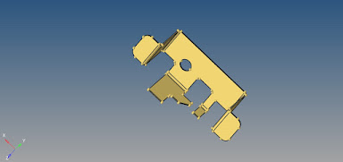
 Holder clip is general purpose component used in daily life. Holder clip is a sheet metal component made up of materials such as steel or Mild steel.  Objective- To Mesh the given component as per required criterion. Methodology-   Import the geometry into solver deck Firstly delete the solids in the geometry Now extract the midsurface from the geometry from Geometry panel>midsurface Before going further to mesh component, cleanup is been carried out> deleting the surface and edge fillets from defeature panel. The final mesh is generated as per requirements. Procedure-  Conclusion- Mid surface extraction is successfully carried out. 2D mesh generated fulfills the required parameters. Author- Shubham Gangadhar Kurhade email-  sgkurhade2511@gmail.com LinkedIn-  Shubham Kurhade Contact- 9511846581